Posts

Showing posts from 2018

OVERHEAD LINE CONDUCTORS

Image
" DIFFERENT TYPES OF ACSR CONDUCTORS " SQUIRREL CONDUCTOR : CONDUCTOR SIZE = 20 SQ MM CONDUCTOR AMPACITY = 107 AMPS APPLICATION = USED IN 440V DISTRIBUTION  LINES.        2. WEASEL CONDUCTOR : CONDUCTOR SIZE = 30 SQ MM CONDUCTOR AMPACITY = 138 AMPS APPLICATION = USED IN 11 KV TRANSMISSION LINES.                                                     3. RABBIT CONDUCTOR : CONDUCTOR SIZE = 50 SQ MM CONDUCTOR AMPACITY = 190 AMPS APPLICATION = USED IN 11 KV TRANSMISSION LINES.                         4.DOG CONDUCTOR : CONDUCTOR SIZE = 100 SQ MM CONDUCTOR AMPACITY = 290 AMPS APPLICATION = USED IN 33 KV TRANSMISSION LINES.                                     5. WOLF CONDUCTOR  CONDUCTOR SIZE = 150 SQ MM CONDUCTOR AMPACITY = 400 AMPS APPLICATION = USED IN 33 KV TRANSMISSION LINES.                                  6. PANTHER CONDUCTOR : CONDUCTOR SIZE = 200 SQ MM

Electrical Facts & Information

Image
Largest Power Plant :   3 Gorges Dam  - China  = 22,500 MW (hydro power plant)  It has 32 Generators each capacity of 700 MW. largest hydro pp in world. Generator Specifications : Rated power : 778 MVA. rotor speed : 75 rpm rotor poles : 80 generated voltage : 20 KV 3 Gorges Dam  Taichung Power Plant - Taiwan = 5,788 MW (Coal Based PP) it has 10 - 550 MW alternators & 4 - 72 MW  alternators .                                                  Taichung power plant MUNDRA POWER PLANT - GUJARAT = 4,620 MW (COAL based ) it uses Super Critical Technology alternators it has 6 - 330 MW & 3 - 660MW alternators .                  Generator Specifications : Rated capacity = 776.5 MVA  Rated Power = 660 MW  Stator Voltage = 22KV Stator current = 20377 Amps field current = 4476 Amps rated speed = 3000 Rpm cooling = water + hydrogen  manufacturer = Dongfang Electric machines ltd (china)                                         

Transformer Preventive Maintennace

Image
PPM for Transformer: Informing department and getting Approval . Ensuring incoming & outgoing breakers in off position. Applying LOTO Tags . Using proper PPE while carrying out PPM. Cleaning T/F with dry cloth . check & Reticify Oil leakages.  check silica gel condition. check OTI & WTI control wiring & tightness . check OLTC Belt condition . Checking Manual operation of oltc . checking buccholz's relay alarm & trip test. checking for damaged nuts & bolts. check Neutral to Earth Resistance . HT To LT Megger values need to check .  2500 KVA TRANSFORMER

Capacitor Bank details

Image
          Capacitor Bank      Capacitor bank can be connected in LT or HT side    In   Industries it is connected in HT side due to High rated motors   installed and requirement of Reactive power is more.   Where as in commercial Buildings Capacitor banks of smaller capacities are placed in LT room .          Why we need Capacitor Bank?     Capacitor Bank improves power Factor gives Leading PF, helps   industry from getting low PF penalties from Electricity Board.     Reduces losses.       Improves motor performance.     P= V I cosǾ, PF inversely proportional to voltage & current.  HT Capacitors in Industrial Sector   In industries HT Capacitors are used & are placed at Switchyard.   HT capacitors placed in between Series reactor & Residual voltage Transformer.      HT capacitor bank rated at 40KV.   Capacitor bank has single Capacitor unit for each phase ( RYB ).   Capacitor bank outgoing connected to Residual voltage transformer and

ELECTRICAL DATA

Image
STANDARD VOLTAGES: VOLTAGES (KV) VOLTAGE LEVELS VOLTAGE REGULATION 3.3 , 6.6 ,11KV LOW VOLTAGE   (LV)     +- 6% 22 , 33 , 66 KV HIGH VOLTAGE   (HV)      +- 9% 110, 132 , 220 KV EXTRA HIGH VOLTAGE (EHV)    +-12.5% 400 ,765,1000KV ULTRA HIGH VOLTAGE (UHV)    +- 15% FREQUENCY VARIATION = +- 3% ( 48.5 – 51.5 HZ )

DISTRIBUTION TRANSFORMER

Image
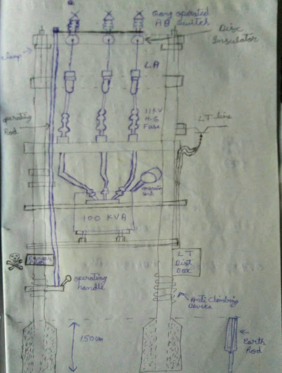
POLE- MOUNTED DISTRIBUTION TRANSFORMER      Front view of pole mounted transformer with all electrical Equipments.   The 11KV Distribution line surpasses all the Electrical Equipment's Transformer finally steps down voltage to 440V and distributes to domestic consumers. SIDE VIEW OF DISTRIBUTION TRANSFORMER

First Independence Day celebrations

Image

220 KV Transmission Line

Image
Transmission line consists of  1)  STRAY  INSULATOR 2) LIGHTNING ARESSTOR 3) COUPLING CAPACITOR 

VOLTAGE LEVELS IN LT SIDE

Different Levels of 3 Phase & Single PhaseVoltages Voltage Levels 3 Phase Voltage   1 Phase Voltages Maximum System Voltage                   440V           254V Highest System Voltage                   433V            250V Normal System Voltage                   415V           240V Normal System Voltage                   400V           230V Minimum System Voltage                   380V           220V

CABLE GLAND SIZES

Image
Cable Gland Sizes for Different Cable Sizes   CABLE     SQMM      Cable Gland Size         (mm) 1.5 12 1.5 16 2.5 19 4 22 6 22 10 25 16 28 25 32 35 32 50 35 70 38 95 45 120 45 150 50 185 50 240 57 300 63 400 70 630 100